Product Description
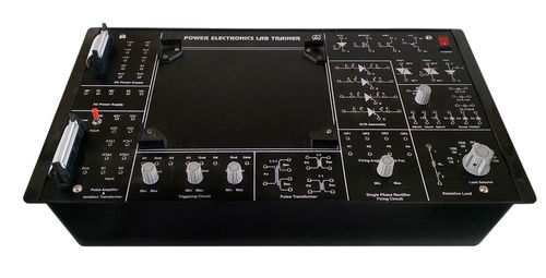
| Power Electronics Trainer Kit |
| IEEE Symbol of all components to be provided on the PCB |
| All components should be visible on top side of PCB |
| Onboard passive active components should be provided Should cover different power electronics devices ie Thyristors |
| Characteristics and application study of different types of power electronics devices ie THYRISTORS SCR TYN604 TRIACBT136 DIACDB3 UJT2N2646 PUT 2N6027 MOSFETIRFZ44N BJT PNPBC557 BJT NPN BC547 |
| Oscillator IC NE555 with a tuning pot should be provided |
| 14 TAP Transformer with different number of windings |
| Pulse Width Modulation section with a tuning pot to display HPWM LWPM |
| MOSFET bridge circuit with a motor output |
| Resistor bank 29 Resistors |
| Range from 100 to 90 K 4 watt |
| Different wattage Resistors 8 Resistors |
| Range from 012 o Range from 12 W to 5 W |
| Capacitor Bank 11 capacitors Range from 001F to 220nF |
| Potentiometer bank 4 pots |
| Range from 1000 to 500 Diode Bank 10 diodes |
| 1N4007_5 nos 1N5819_5 nos |
| Power Supply 30V AC 12V DC |
Versatile Experiment ModulesExplore up to 10 different modules including core components such as diodes, IGBT, SCR, MOSFET, capacitors, inductors, and transformers. Modular circuits and fault simulation capabilities allow students and instructors to conduct comprehensive studies of power device characteristics and converter applications within a controlled lab environment.
Comprehensive Safety FeaturesMaintain optimal operational safety with overload protection, fuse protection, and built-in short-circuit and reverse polarity protection. The kit's input fuse rating of 2A (fast blow) and natural air cooling ensure stable and secure experimental conditions, preventing damage to sensitive components and maximizing user safety.
Accessible and Accurate Measurement ToolsBenefit from the convenience of multiple test points, banana socket connectors, and isolated output terminals. The trainer includes both analog and digital display meters for precise voltage and current readings within a range of 0-30V and 0-3A, supported by 1% measurement accuracy. All experiments are guided by a comprehensive manual.
FAQ's of Power Electronics Trainer Kit:
Q: How does the Power Electronics Trainer Kit ensure user safety during experiments?
A: The trainer kit features overload and fuse protection, short-circuit and reverse polarity safeguards, and a 2A fast blow input fuse. These safety features, along with natural air cooling, protect both users and equipment during lab operations.
Q: What practical experiments can be performed using this trainer kit?
A: This kit allows for hands-on study of core power device characteristics, converter circuits, and fault simulations through its up to 10 modular experiment modules and comprehensive user manual, making it ideal for academic demonstrations and laboratory research.
Q: Where is this trainer kit primarily used?
A: Designed for indoor environments, the Power Electronics Trainer Kit is typically used in academic labs, research facilities, and technical institutions for studying and demonstrating power electronics concepts.
Q: When should the kit be stored and under what conditions?
A: After experiments, store the kit in conditions between 5C and 40C, and ensure humidity remains below 80% to preserve the integrity of its components and panel layout.
Q: What are the benefits of using both digital and analog meters in this kit?
A: Having both digital and analog display meters allows users to track voltage and current readings with high accuracy (1%) and flexibility, ensuring reliable data collection during experiments.
Q: How do users connect experiment circuits to the trainer kit?
A: Users can easily connect circuits through banana sockets and test leads provided on the panel. The multiple accessible test points and isolated output terminals enhance connectivity and measurement convenience.