Product Description
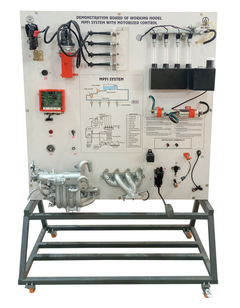
DEMONSTRATION BOARD OF WORKINGMODEL MPFI SYSTEM WITH MOTORIZED CONTROL
Technical Specifications:
Theinstruction board must be connected to a 220V AC socket, which Internallyconverts to 12V DC, enabling the board to function without a battery. The boardfeatures actual components from the electronic fuel injection System todemonstrate the structure and functionality of the engine's fuel system.Instruction board designed for the electronic fuel injection system of gasolineengines (MPFI) Components are ntegrated into a color-coded circuit diagram,making it operational. A fully functional engine fuel injection system ismounted on a Color printed board to showcase its structure and operationalprocess. Detection terminals are available for operators to assess varioussensors, actuators, and electrical signals for the engine control unit. Thesesignals include resistive, voltage, current, frequency, and waveform signals,all represented on the printed circuit diagram. The instructional board servesas a practical tool for understanding the electronic fuel injection system. Itenhances learning by providing a hands-on experience with real components.Students can engage with the system, fostering a deeper understanding of enginecontrol mechanisms. Users can induce faults such as line breaks, groundingshort circuits, Improper contacts, or open circuit faults, with the ability toadjust the quantity and type of faults.
Comprehensive Learning Tool for Automotive EducationThis MPFI system model is meticulously engineered for educational purposes, enabling students to observe real-time live operations of a multi-point fuel injection system. It allows for fault simulation, encourages interactive schematic referencing, and includes all key modern engine components. The clear panel design aids understanding, making it ideal for laboratory and technical training.
Safety and Ready-to-Use AssemblyDesigned with user safety in mind, the system incorporates insulated electrical elements and shields on all moving parts. Delivered as a pre-assembled unit, it features a mild steel frame and durable display materials. Lockable wheels and protective features make it both portable and secure for active laboratory use.
Hands-On Experience with Advanced FeaturesStudents and trainees gain hands-on practice with real sensors such as MAP, TPS, IAT, CTS, and O2 sensors. Fault insertion switches and accessible test measurement points foster diagnostic skills development. Demonstrating both manual and partially automated processes, this model is an effective gateway to automotive electronics and fuel systems.
FAQ's of WORKING MODEL MPFI SYSTEM WITH MOTORIZED CONTROL:
Q: How does the motorized MPFI training model demonstrate engine operation and fuel injection processes?
A: The system uses a single-phase induction motor to simulate engine drive while demonstrating live fuel injection control via multiple sensors and injectors. The integrated schematic and live components allow users to observe, interact, and understand sequential fuel delivery and sensor feedback.
Q: What educational benefits does this MPFI system offer to students and trainees?
A: It provides hands-on exposure to MPFI fundamentals, real-time fault diagnosis, and practical measurement exercises using test points and fault insertion switches. This approach strengthens technical understanding and diagnostic skills relevant to modern automobile engineering.
Q: When should the fault simulation facility be used during training?
A: Trainers and learners can activate fault switches during demonstration sessions to expose or resolve system issues. This controlled process teaches correct diagnostic techniques and logically tests understanding of automotive electronic systems.
Q: Where is this MPFI training equipment typically installed or used?
A: This model is optimized for automobile engineering laboratories, technical institutes, and training centers. Its floor-standing, lockable-wheel frame ensures easy relocation and secure placement in classroom or lab environments.
Q: What safety features are included in the model for laboratory use?
A: The unit is constructed with insulated electrical components, fuse and overload protection circuits, and protective shields on all moving mechanical parts, ensuring user safety during demonstrations. Its sturdy build offers additional stability and reduces accident risk.
Q: How is the system powered and can it be used internationally?
A: Powered by a standard Indian 230V AC supply, the model includes customizable power options for worldwide compatibility. Internal electronics operate at 12V DC for additional safety and versatility.
Q: What is the process for measuring sensor outputs or fuel injection signals?
A: Students can use dedicated test points on the control panel to measure sensor or injector signals during live operation. The annotated schematic assists in locating circuits and interpreting measurement readings effectively.









 Send Inquiry